Stable Synchronization

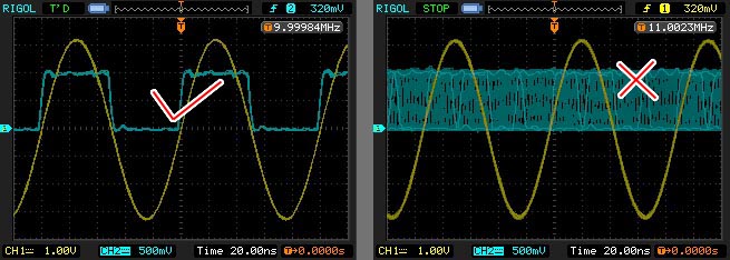
In the above figure, the yellow trace is the Output Signal from Hantek 3x25, and the blue trace is the Synch Signal from it. On the left figure we can see yellow and blue trace are nicely In-Phase or In-Synch, where on the right figure, both are not In-Synch, ie no correlation between both's phases. Hantek use mechanism of Number of Points (nPts) and Number of Periods (nPer) to generate DDS signal. It means, the software needs to fill nPer of signal cycle in nPts of data array. Let say nPts = 4000, nPer = 40 (freq request of 2MHz), and we try to send sine signal to Hantek. it means there should be 40 cycles of sine in 4000 data points (Integer array) created by software and then later to be sent to Hantek, in this case, in each 100 data points, there's a complete 1 cycle of sine signal. Hantek use this mechanism to enable it to produce any number of frequencies albeit its clock limitation only divisible by integer number (200MHz / n, where n is integer number = 1,2,...,97656). So for the above case, nPts / nPer (4000 / 40) is exact integer value, so the sine (Output) signal will be in-line (In-Synch) with Hantek clock (Synch Signal). but what about if we request the frequency that will result in non integer division of nPts / nPer. Let say we request for frequency 3MHz, Hantek will return nPts = 4066, nPer = 61, ie 66.66 points per period (4066 / 61). This is non-integer division and hence, Hantek clock will be unable to get in-line with 66.66 points. By nature (hardware or firmware?), Hantek clock only capable to get inline with 66 or 67 points of data per period. This results in slight deviation from our frequency request (3MHz), ie for exact 3MHz eqv to 66.66 points/period, theoretically, Hantek clock should be 199.967213 MHz (clock = freq * (nPts / nPer)), but practically its not, we have to round off to 66 or 67 nPts / nPer. using "Mark Madel's Estimation", the Hantek clock for frequency request 3MHz will be 200MHz, so our 3MHz signal request will only be able to synchronize with Hantek clock (or Synch Signal) at freq 3.03MHz (200MHz / 66) or at freq 2.985MHz (200MHz / 67). So, in Goltek Controller, if Stable Synch feature is enabled, the program will round off this non integer division into integer division, so instead of using 66.66 points per period to generate 1 cycle of sine, the program will round it off to 67 points which result in lower frequency output compared to the requested value. So there will be compromise, if you want to get In-Synch with Hantek clock, you have to accept some frequency deviation (3MHz -> 2.985MHz), but if you need the exact 3MHz reproduction from Hantek, then you will not be able to get In-Synch with Hantek clock (Synch signal). Your specific application may prefer either one, to get In-Synch, or exact (closest) frequency output as requested, but not both, except at lower frequency (<=1MHz) or at some specific higher frequencies that's by nature are integer divisible (sweet spot) to the Hantek clock for example 2MHz, 4MHz, 5MHz, 10MHz, 20MHz, 50MHz or 100MHz.
In-Synch (In-Phase) Signal

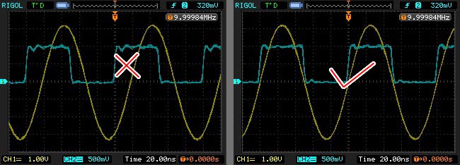
After the discussion of Stable Synch above, once we get the Output Signal and Synch Signal synchronized using "Stable Synch Technique", we have to deal with another hiccup in Hantek hardware, ie Out Of Phase Signal. Although now we have Output and Synch Signal's phase to be in correlation, but they are not at the same phase, esp. at higher frequencies (even at lower frequencies with closer inspection). Without any mean of compensation, we will have the signal as shown in the left figure above, ie the Output will be lagging compared to Synch signal. At some application, this lag is not desirable, and we want the signal like the one shown in the right figure. Then how do we get around this? Luckily we have, in software programming discipline, a classical technique known as data (array) shifting...
Array Shifting

In DDS signal generation, wave is constructed from values in an array of data. in this form, it will be sent to Hantek 3x25 to be used for generating signal. We can put any values in the array to create arbitrary wave, but for simplicity explaining out of phase condition and its solution, we'll take the case of sine signal using 8 values, or points (or elements) in the array. Usually we will calculate sine signal starting from angle 0° indicated by point 0 (P0) at 0°, P1 @ 45°, P2 @ 90° and so forth until P7 @ 315° in the left figure above. we then send this data points to Hantek. Hantek will execute this data starting from P0, but unfortunately, the Starting Of Execution (SOE) is not the same time as the Synch Signal rise time. There will be a timing delay of dt eqv to around 45°-90° (lets assume 90°) of phase lag in SOE (or Signal Lag, or Lead?) as shown in the left figure. To compensate for this delay, we need the P0 to be executed ahead of SOE, how do we do this? Array Shifting! from the left figure, we know SOE is at 90° lag compared to Synch Signal, where our sine signal is at P2 for that angle which will be executed another 90° angle after SOE, we need P2 to be the SOE, so we will left shift our data array 2 elements, ie P0 and P1 got pushed to the last elements, and P2 got into 1st position, ie newP0 = oldP2, as shown in the middle figure. When we send this shifted array to Hantek, it will SOE at our new P0, ie sine at 90°, with 90° of SOE lag, they are now (Output and Synch) "in phase" and the old P0 (and P1) is now executed "virtually" ahead of SOE as shown in the right figure. The conversion from phase lag into how many data shifting need to be done is calculated in the software, but in order to shift correctly, Goltek Controller Software will rely on Phase Profiling (file) to do this job which is discussed in Phase Profile Concept and File Format.
any comment, improvement
and suggestion,
please contact me at soasystem@yahoo.com
well, too sad if you don't have a back button