Flatness Control and Bandwidth Limitation
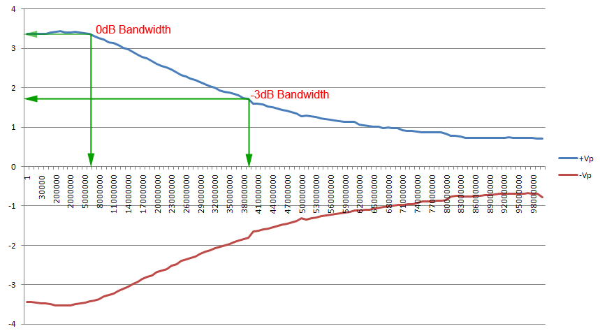
Here we discuss another weakness of Hantek DDS3x25 device, ie its bandwidth limitation and output attenuation profile. I've made a rough study on Hantek output profile, ie how much voltage swing its capable of at certain frequency. The figure i obtained is shown in the above V vs. Freq graph figure. The method of my testing can be found in Rigol DS1052E Flatness Revisited Using Peak Detector which i originally published in eevblog. Please note that it is assumed that the DSO output i'm using for the testing is flat up to the maximum frequency tested, ie 100MHz, which is i believe NOT, so bear in mind that the result above is not that accurate, its only suitable for educational purpose and as close as we/i can get to the Hantek output profile.
We can see clearly from the above figure that the Hantek output is not flat, ie the output will attenuate as the frequency is increased. If we are to specify the output bandwidth, at 0dB (zero) attenuation, the Hantek bandwidth is only up to around 6MHz, and at half of the maximum amplitude, ie -3dB attenuation, the Hantek is only spec'ed as 38MHz. This means, if you want to use the device for testing purpose with flat amplitude at 3.3V, you only can set the frequency up to 6MHz, beyond that, you will get lower amplitude which will affect the result of your testing. The same if you want to make a testing at around 1.65V, the limit is only up to 38MHz. This is hardware limitation and nothing we can do in software to increase the amplitude beyond the cone shaped envelop above. We can however, if we need greater amplitude, to build our own amplifying device to break this rule, one simple example is like my diy amplifier here which i call it 10x25 Amplifier since it can produce output of 10Vpeak at 0dB (5V @ 38MHz) when feed by Hantek output and ±12V power supply. But still with its amplified output, its profile will still follow the cone envelop since it inherit the shape from the Hantek output above (THS3091 opamp flat respond up to 100MHz, G = 5). For a really flat respond out of Hantek, we can find a way in hardware level to build a fancy respond device to compensate, but that is another story.
What i'm trying to do here is to find the solution in software level on how to create a flat respond from Hantek 3x25 output even without external add-on device like my amplifier mentioned above. Since we cannot go beyond the profile envelop, so we have to (and only can) work in the envelop region. But first, we need a similar file as Phase Profile File, but instead of storing phase data, the Signal Profile File will store the output amplitude (attenuation) that made up the graph shown above. Once we get the profile, we can program in software by "Method Of Scaling" (see below) to get flat respond out of Hantek. One of the main purpose of Flatness Control is that we dont have to keep track of how much the device will attenuate at certain frequency (graph above) and manually compensate in the software input to reach a desired level, what we want is by setting a volt level in software, say 1.65V, we can pretty sure that's the volt level that the Hantek is producing at any given frequency, be it at max bandwidth of 38MHz, or at 10MHz, 1MHz or even 100 or 1Hz!. we can get rid of manual scaling and recompensating work and can concentrate on our main job/project and ensure reliable result. Let's look how it works...
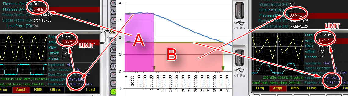
The above middle figure is cropped portion of the topmost graph profile figure. To activate Flatness Control in Goltek Controller Software, we go to Utility Panel and Set it to ON, and set the desired Flat Bandwidth (BW), let's say we want to work at max amplitude capability of the Hantek, ie 0dB, so we set the Flatness BW to 6MHz (left figure). by setting this, program will activate region A (purple rectangle region in middle figure), meaning we will only be able to work in region A, program will not allow you to set the frequency or amplitude past/outside that region, in this case 6MHz and 3.36V max, this is to ensure we are working in the flat region of 6MHz. We can set to lower frequency and amplitude value while in that region, and the program will do the necessary (vertical) scaling to ensure the Hantek flatness and output is what we are setting in the software. Outside this region, program will be unable to do the scaling since it will overflow the Hantek hardware resolution (12 bit) and how the internal mechanism of this program works. and most importantly it will not ensure flat output, which is the whole point about, hence the (frequency and amplitude) limitation applied. Similarly when we want more bandwidth, we set in Flatness BW for higher frequency, lets say 38MHz, then we will switch to region B (orange rectangle, some overlapping with Region A). in this region, we will only be able to work at lower amplitude to ensure flatness, so bear that in mind that there's compromise we have to make (lower amplitude). Even though Hantek is capable of doing more at lower frequency (higher amplitude) indicated by white triangle above region B (to the right of region A), but for the sake of flatness, the program will simply not allow you to. To get back full region/envelop of Hantek output capability, simply turn the Flatness Ctrl OFF, you'll get them all, except.... flatness.
Hantek Value vs. Real Value
Now let me describe a little bit more detail into how the software achieves this "virtual" flatness effect. One aspect is already described above, ie avoiding user to use the full envelop of Hantek profile (Output) by simulating (limiting) lower amplitude at lower frequency (even though Hantek can do more). Another aspect is how the internal calculation is made, ie using some simple "Method Of Scaling". But before that, lets look at the real data that is sent to Hantek...
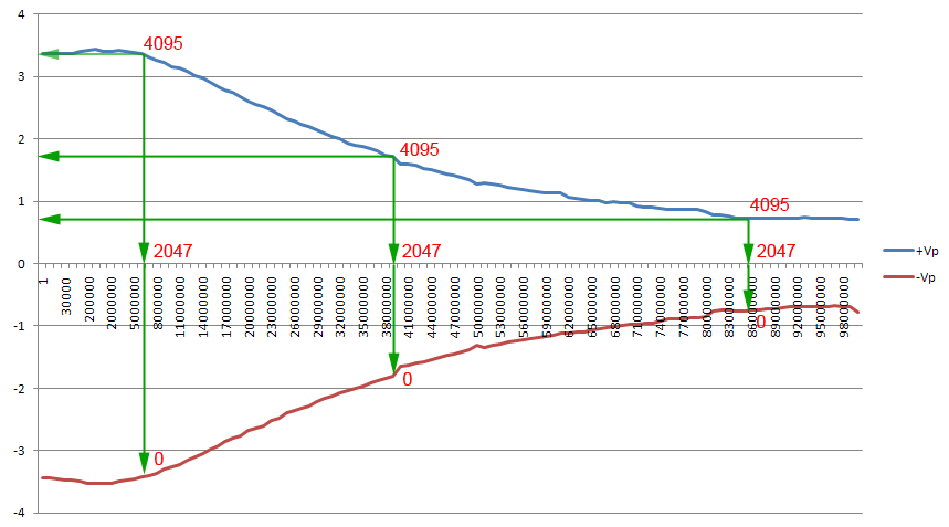
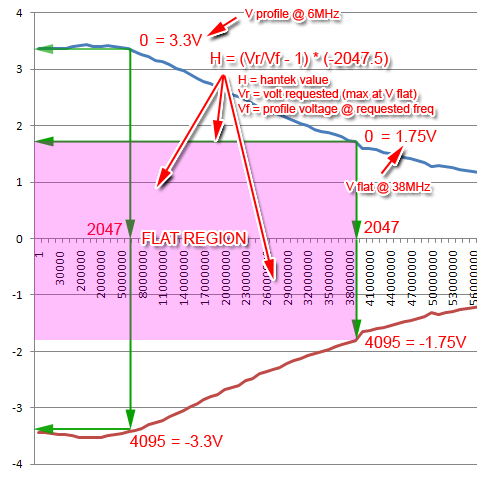
Data (array) that is sent to Hantek for signal generation is not what we think it is. We might think that we have to send volt values for Hantek to generate a signal like 3.5V, 3V, 1V, 0V, -1V, -3V, -3.5V? NO. We have to translate it to Hantek "language" or value, not the value that we like or used to or familiar with. Since Hantek is a 12bit resolution device, so it will only accept 12 bit binary values (there's 4096 values 0 - 4095). Hence we need to translate 3.5V to -3.5V range into 0 - 4095 range. With simple mathematics, that is easily achievable. And to make it worst, Hantek value is upside down, ie 3.5V eqv 0, and -3.5V eqv 4095! with 0V will be eqv to the middle of 4095 / 2 = 2047. But to avoid our mind get upside down, we just assume positive 3.5V eqv to 4095, negative 3.5V eqv 0 and middle 0V eqv 2047 as shown above figure (in reality 0 should be at the top, 4095 at the bottom). OK, we have not yet reach "The Method of Scaling" that i want to talk about for flatness control, this is just typical translation that we have to make from real world value to what Hantek understand. But let's look further in the above figure. During profiling process, we will request Hantek to output ±3.5V full voltage swing at any frequencies. But a flat ±3.5V swing throughout frequencies range is only theoretical, what we actually achieve is a non-flat signal. We keep giving Hantek the same full value range of 0 to 4095 at any frequency but we get different (actual) voltage swing. This is the role of Signal Profile File, to store these (attenuated) voltage values mainly for 2 purposes, 1 is to determine the flat voltage at certain bandwidth, hence will be used as limiting voltage in software, and 2nd purpose is for scaling purpose. How is the scaling for flatness purpose? Let us simplify even more the above figure into the figure below, ie we only consider positive voltage and assume that's the full 12 bit swing, ie 0 - 4095 for the simplicity of formulation...
Method Of Scaling
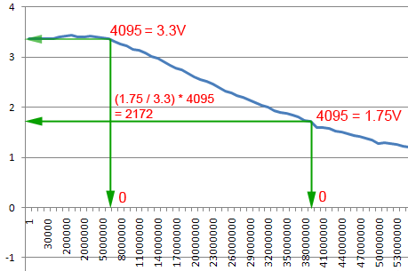
Now as said, during profiling process we keep sending the same 4095 (max) value to Hantek, but at different frequency we will get different voltage output. when we send 4095 value at 6MHz, we will get 3.3V out of Hantek, but we cannot expect the same voltage when we send the same 4095 at 38MHz, it will be different, ie only 1.75V. In the profile file, this voltage values is that matters, not the 4095 value, volt to 12bit translation only occurs in software using scaling of this values of voltages. How the scaling? well, let's assume we are dealing with 38MHz bandwidth flat voltage. from the profile, we (and the program) know that the voltage profile at 38MHz is 1.75V, this value will be the key (flat voltage) for the scaling. To get the flat voltage of 1.75V at different frequency, we get the flat (key) voltage divided to the profile voltage at the requested frequency. Let say we want to get flat voltage at 6MHz. The voltage profile of 6MHz is 3.3V, so we divide (key / profile) * 4095, ie (1.75 / 3.3) * 4095 = 2175. So if we send value 2175 at 6MHz to Hantek, we will get the output voltage the same as the max (profile) voltage at 38MHz, ie 1.75V. By this simple scaling, we have achieved flat voltage between 6MHz and 38MHz, simple! the same method will be used for other frequency less than or equal to 38MHz, and guess what value should we send to Hantek to get the flat voltage of 1.75V at 38MHz? right! its the [key / (profile @ 38MHz)] * 4095 = (1.75 / 1.75) * 4095 = 4095! the max Hantek Value! as mentioned, this is highly simplified version. the real formulation is a bit messier than this. I will just describe it in the figure below, enjoy!
and lastly i forgot to mention that, we can use method described above to profile and output flat signal even if we have additional intermediate hardware plugged into the Hantek to modify its output (like my diy amplifier). all we have to do is to profile the add-on output, save it in a Signal Profile File, load it into Goltek Controller, and we can see that the Goltek will read and display the value based on that profile. I've included (profile10x25.csv) in \profile folder in Goltek App folder as an example for my diy amplifier signal profile. (in earlier version it was profile9x25.csv, i dont know why i got mixed up with 9x instead of the correct 10x :P)
any comment, improvement
and suggestion, please contact me at soasystem@yahoo.com
well, too sad if you don't have a back button